
0%

Choosing Combined Drill and Countersink Bits in 2026 requires more than matching a diameter to a screw. The right tool must drill a clean pilot hole and create a consistent seating surface in one controlled operation. Small details matter. Material, flute geometry, countersink angle, coating, shank design, and depth control can change the result significantly.

Machining educator John Saunders explains, “A combined tool earns its value when setup time falls without sacrificing hole accuracy.” This practical view remains important for workshops, maintenance teams, and production lines. A premium-looking bit may still perform poorly in hardened steel, abrasive composites, or soft aluminum. The workpiece remembers every mistake through burrs, chatter, oversizing, and uneven screw seating.

This guide examines how to choose Combined Drill and Countersink Bits for modern applications. It considers high-speed steel, cobalt, and carbide options, along with titanium-based coatings and multi-material performance. It also compares fixed-depth designs with adjustable systems, especially where repeatability matters. Correct speed and feed settings will receive attention, because even a well-designed tool can fail under excessive pressure.

There is no universal best bit. That is easy to forget. Real selection often involves compromise between price, durability, speed, and finish quality. A careful buyer should test the tool on the actual material, inspect the first holes, and monitor wear during production. Specifications provide direction, not certainty. In 2026, the most reliable choice will combine verified dimensions, suitable geometry, responsible manufacturing, and evidence from real workshop use.
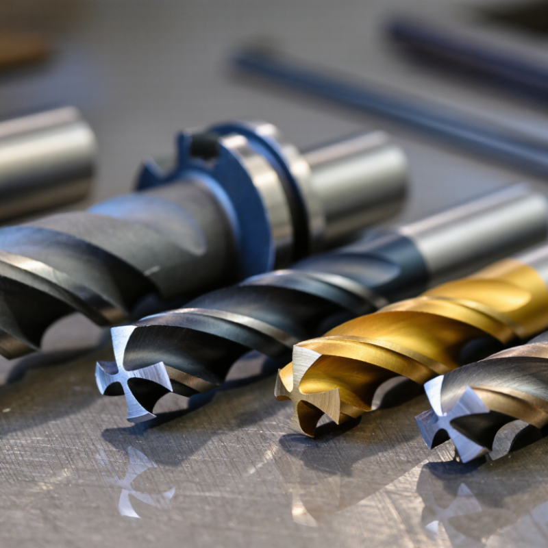
How to Choose Combined Drill and Countersink Bits in 2026?

Define the Workpiece: Wood, Aluminum, Steel, and Stainless Steel

When choosing combined drill and countersink bits in 2026, identify the workpiece before comparing coatings or prices. Wood usually accepts a sharp, moderate-angle bit with open flutes. Soft pine cuts quickly, but it can splinter around the countersink. I reduce pressure as the shoulder enters the surface. A scrap board reveals more than a product label. Harder hardwoods need steady feed control. Too much force can burn the hole.

Aluminum requires clearance for soft, sticky chips. A bit with polished flutes and suitable cutting geometry helps prevent clogging. I use cutting fluid only when tool guidance permits it, then clear chips frequently. Steel demands greater rigidity and slower speed. A loose drill can leave an uneven seat for the screw head. The countersink may look clean while the pilot hole runs off-center. Check both surfaces.

Stainless steel is less forgiving. Heat builds quickly, especially when the bit rubs instead of cutting. Use firm pressure, controlled speed, and fluid designed for metalworking. Do not pause with the bit spinning in one spot. That mistake can harden the surface and make the next pass worse. I still test on an offcut, because published charts cannot predict every alloy, thickness, or machine. A general-purpose bit may work once, then disappoint.

Match 118° or 135° Drill Points to Material and Hole Size

Choosing a combined drill and countersink bit starts with the drill point, not the countersink. A 118° point suits mild steel, aluminum, brass, and softer plastics. It cuts readily and reduces starting pressure. A 135° split point holds better on stainless steel and harder alloys. Its flatter profile limits walking and lowers thrust during entry.

Material choice matters because global steel production reached about 1.89 billion tonnes in 2023, according to World Steel Association’s World Steel in Figures 2024. Many workshops therefore face mixed steel grades, not one predictable material. For a 3–6 mm hole in mild steel, I would test a 118° bit at a moderate feed. For a larger hole, or a hard surface, the 135° option usually gives steadier engagement. Not always.

Hole size changes the practical decision. Small diameters flex easily, so a split-point 135° design can improve location accuracy. However, an overly aggressive point may scrape in thin aluminum. The 2024 U.S. Cutting Tool Consumption report from AMT and USCTI valued domestic cutting-tool consumption at roughly 2.6 billion dollars, showing how widely these operations are used across manufacturing. Still, data cannot replace a test hole. Check burr height, entry marks, chip shape, and countersink depth after five parts. My first setting is often conservative, then adjusted by sound and surface finish. That habit is imperfect, but it prevents one angle from becoming a lazy rule.

Choose 82°, 90°, or 100° Countersink Angles for Fastener Standards

Choosing the countersink angle is more important than choosing a longer bit. An 82° angle suits many inch-based flat-head fasteners, especially under ASME B18.6.3. A 90° angle generally matches ISO metric countersunk screws, including ISO 10642 designs. A 100° angle supports thin sheet metal and many aerospace-style flush fasteners. The wrong angle leaves a sharp rim, poor seating, or a proud fastener head. It can also weaken a thin panel.

I have seen operators select 90° by habit, then discover that an 82° screw rocks in the hole. That small mismatch wastes time. UNIDO’s 2024 Industrial Development Report places manufacturing near 16% of global GDP, showing why repeatable hole preparation matters across industrial production. Market research also continues to show strong demand for metal-cutting tools, but broad market growth does not replace checking the fastener drawing. Standards matter more than sales charts.

Tips: Match the bit angle to the fastener specification, not the material alone. Measure the pilot diameter and test one hole on scrap. Use a combined bit only when chip clearance remains adequate. I prefer a controlled feed and a light final pass. Too much pressure creates a wide, uneven countersink. Recheck the drawing, especially when switching between metric and inch hardware. A visual check helps, but it is not enough. Surface finish and head height still need measurement.

How to Choose Combined Drill and Countersink Bits in 2026? — Choose 82°, 90°, or 100° Countersink Angles for Fastener Standards
Countersink Angle Common Fastener Standard or Use Typical Fastener Type Best Material or Application Selection Guidance
82° Common inch-system flat-head geometry; associated with ASME/ANSI inch fastener practice, including ASME B18.6.3 machine screws Inch flat-head machine screws, wood screws, and many general-purpose self-tapping screws Steel, aluminum, wood, plastics, and general fabrication Choose an 82° countersink when the fastener head is specified as 82°. It is usually the first choice for U.S. inch-based hardware.
90° Common metric flat-head geometry; ISO 7721 specifies the countersunk head form for metric countersunk screws Metric countersunk machine screws, commonly ISO metric fasteners General machinery, sheet metal, fixtures, and precision assemblies Choose a 90° bit for metric fasteners whose drawing or specification calls for a 90° included angle.
100° Common aerospace and thin-sheet countersunk geometry; used in aerospace fastener systems such as NAS 1097-type applications 100° flush-head aerospace screws and reduced-head countersunk fasteners Aircraft structures, thin aluminum sheet, composites, and applications requiring a shallow flush head Choose a 100° bit only when the fastener head and engineering specification require 100°. Do not substitute 82° or 90° without checking head contact and remaining material thickness.
Typical Through-Hole Starting Sizes for Combined Drill and Countersink Selection
Fastener Size System Typical Medium-Clearance Hole Suggested Countersink Angle Practical Use
M3 Metric 3.2 mm 90° for standard metric flat-head screws Small fixtures, electronics hardware, and light sheet-metal assemblies
M4 Metric 4.3 mm 90° for standard metric flat-head screws General machine assemblies and brackets
M5 Metric 5.3 mm 90° for standard metric flat-head screws Machine guards, panels, and structural fixtures
M6 Metric 6.4 mm 90° for standard metric flat-head screws General fabrication and equipment frames
M8 Metric 8.4 mm 90° for standard metric flat-head screws Heavier machine assemblies and mounting structures
#6-32 Inch 0.144 in 82° for common inch flat-head screws Small equipment panels and general-purpose assemblies
#8-32 Inch 0.169 in 82° for common inch flat-head screws Brackets, covers, and light mechanical assemblies
#10-32 Inch 0.196 in 82° for common inch flat-head screws Machine panels and medium-duty fixtures
1/4-20 Inch 0.266 in 82° for common inch flat-head screws Structural brackets and heavier general fabrication
3/16 in aerospace fastener Inch aerospace Verify the specified close-tolerance hole size 100° where required by the aerospace fastener specification Thin aerospace sheet and flush structural applications
Hole sizes shown are typical medium-clearance starting values, not universal requirements. Always confirm the fastener drawing, applicable standard, fit class, material thickness, countersink depth, and required flushness before production machining.

Compare HSS, M35 Cobalt, and Carbide for Heat and Wear Resistance

How to Choose Combined Drill and Countersink Bits in 2026?

Heat and wear resistance should guide your choice. HSS suits mild steel, aluminum, and occasional workshop use. ASM Handbook, Volume 16, reports that conventional HSS loses substantial hardness near 550–600°C. That matters when a small countersink rubs instead of cutting. The tip can turn blue, soften, and leave a rough seat. Use steady pressure, cutting fluid, and short drilling cycles.

M35 cobalt HSS contains about 5% cobalt. This alloy generally keeps its cutting hardness better than standard HSS. It is a practical choice for stainless steel and repeated production work. Field testing still matters. A slow feed can create more heat than a faster, controlled cut. I have seen cobalt bits fail early when operators used dull edges and excessive pressure. Better material cannot repair poor technique.

Carbide offers the highest wear resistance among these options. ASM data places cemented carbide hardness commonly above 1,400 HV, while HSS is much lower. Carbide also tolerates higher cutting temperatures, often around 800–1,000°C, depending on grade and binder content. ISO 513 classifies carbide grades by cutting behavior, not by one universal performance number. That distinction is important. Carbide can chip during hand drilling or interrupted cuts. The 2025 USGS Mineral Commodity Summaries also identifies tungsten as a critical mineral, which may affect future tool pricing and availability. Choose carbide for abrasive materials, rigid machines, and high production volume. For portable work, M35 may be the more forgiving compromise.

How to Choose Combined Drill and Countersink Bits in 2026?

Approximate comparison of heat resistance and wear resistance for common tool materials. Actual performance varies with grade, coating, cutting speed, feed rate, and workpiece material.

Key takeaway: HSS is economical for general-purpose drilling, M35 cobalt provides better heat resistance for harder alloys and stainless steel, while carbide offers the highest heat and wear resistance for demanding production applications.

Set RPM, Feed, and Pilot Depth Using Manufacturer Cutting Data

Choosing a combined drill and countersink bit in 2026 starts with cutting data, not guesswork. Manufacturer tables usually list surface speed, feed per revolution, and pilot depth for each material. Calculate RPM with RPM = cutting speed × 1,000 ÷ π × tool diameter. For a 6 mm tool at 60 m/min, the result is about 3,180 RPM. I still verify the machine’s actual speed, because displayed values can be optimistic.

Feed must match the complete tool profile. A pilot section removes material first, while the countersink creates a wider cutting load. If the table specifies 0.08 mm per revolution, use about 254 mm/min at 3,180 RPM. Reduce feed when the pilot enters a hard skin, interrupted surface, or thin sheet. Keep the pilot depth only slightly deeper than the required hole. Too deep increases rubbing and heat. Too shallow leaves the countersink cutting before the hole is stable.

The 2024 U.S. Cutting Tool Consumption report from the U.S. Cutting Tool Institute and the Association for Manufacturing Technology showed continued volatility in industrial tool demand, reinforcing the need for controlled settings rather than habit. ISO 3685 tool-life guidance also supports recording speed, feed, material, and wear consistently. A practical test uses one dry run, one measured hole, and a quick edge inspection. Watch the chips. Blue chips suggest excessive heat, while long tangled chips suggest poor evacuation. These signs are useful, but not perfect. Manufacturer data should remain the starting authority.

FAQS

How should I choose a combined drill and countersink bit for wood?

Choose a sharp bit with open flutes and a moderate point angle.

What bit features help when drilling aluminum?

Polished flutes and suitable cutting geometry help clear soft, sticky chips.

How should I drill steel with a combined bit?

Use a rigid setup, slower speed, and controlled feed pressure.

What changes when drilling stainless steel?

Stainless steel builds heat quickly when the bit rubs instead of cutting.

When is a 118° drill point suitable?

A 118° point often suits mild steel, aluminum, brass, and softer plastics.

When should I consider a 135° split point?

A 135° split point helps with stainless steel and harder alloys.

How do I select the correct countersink angle?

Match the angle to the fastener specification, not only the workpiece material.

What should I inspect after making a countersunk hole?

Measure the pilot diameter, countersink depth, burr height, and fastener head height.

Conclusion

Choosing the right Combined Drill and Countersink Bits starts with identifying the workpiece. Wood, aluminum, steel, and stainless steel each require different cutting characteristics, so the bit’s geometry and material should match the job. A 118° drill point is suitable for many general-purpose applications, while a 135° split point can improve starting accuracy and reduce wandering in harder materials or larger holes. The countersink angle should also match the fastener standard, with 82°, 90°, and 100° options serving different screw designs.

Material selection affects heat control, durability, and service life. HSS works well for routine tasks, M35 cobalt offers better heat and wear resistance, and carbide is appropriate for demanding, high-volume applications when rigidity is sufficient. Finally, use manufacturer cutting data to set the correct RPM and feed rate, and adjust pilot depth to prevent over-drilling or poor seating. Proper setup improves hole quality, fastener fit, tool life, and overall productivity.

Ethan Carter

Ethan Carter

Ethan Carter is a seasoned marketing professional dedicated to helping businesses understand products, discover practical solutions, and make confident decisions. With a strong background in market research, content strategy, customer engagement, and digital communications, Ethan brings clarity and......